This page is about replacing the main shaft with a newly designed crank as well as gear holder, which can help to solve the issue of slippage of the gear and crank with respect to the main shaft.
The following shows the T-shaped crank in the pre-assembled main shaft in the version covered in the workshops (refer to slides in Teachers Training (2021-04-05))
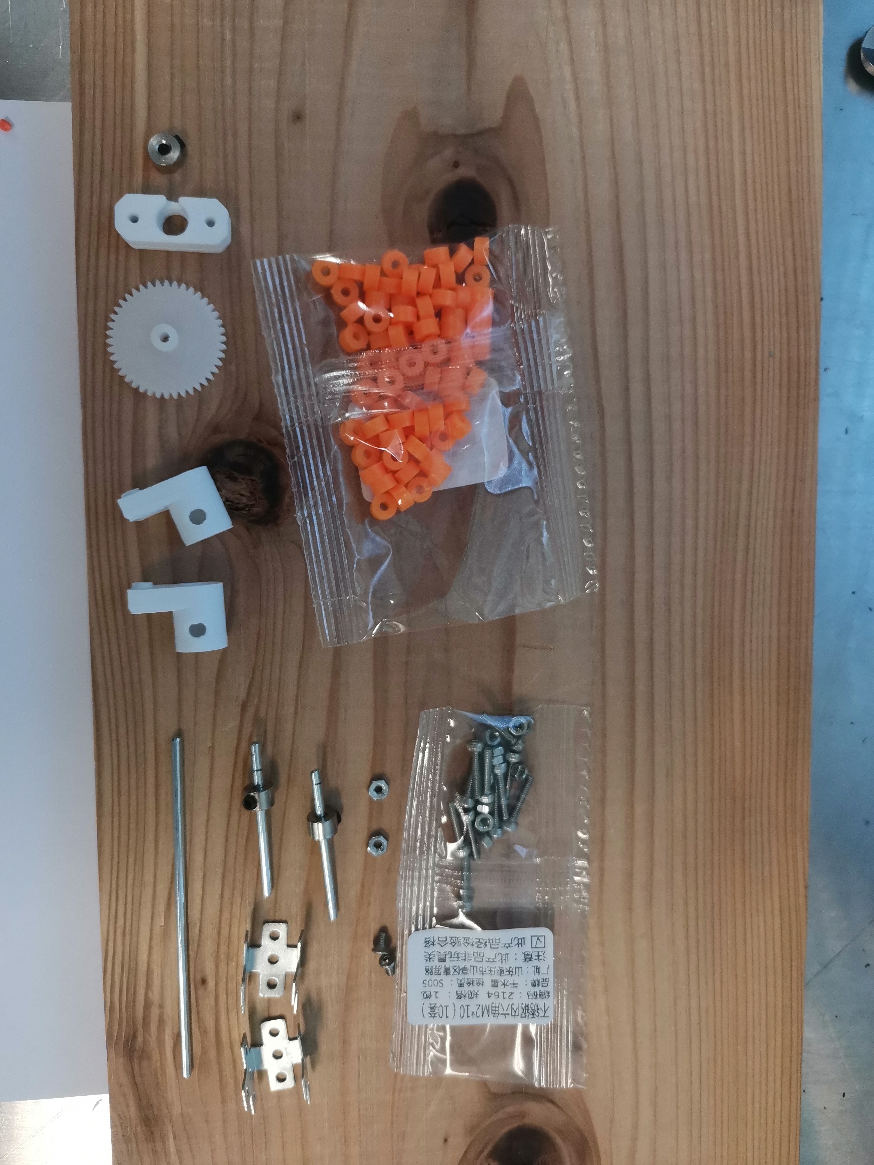
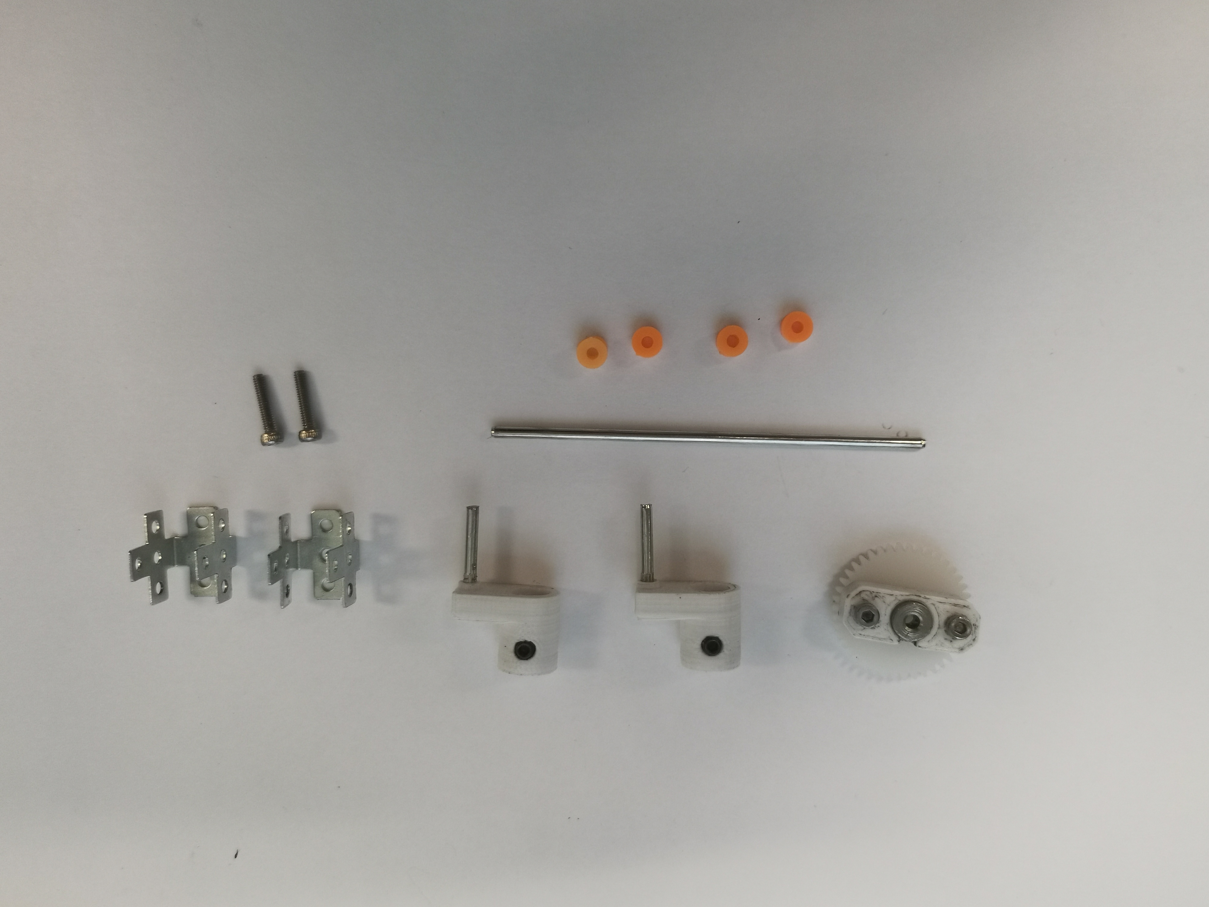
Components for the assembly
| Name | Quantity | Notes |
|---|---|---|
| Crank | 2 | |
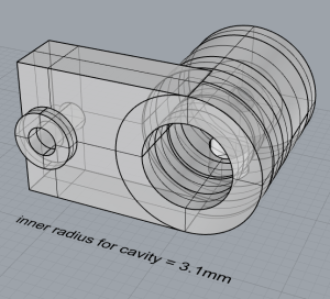
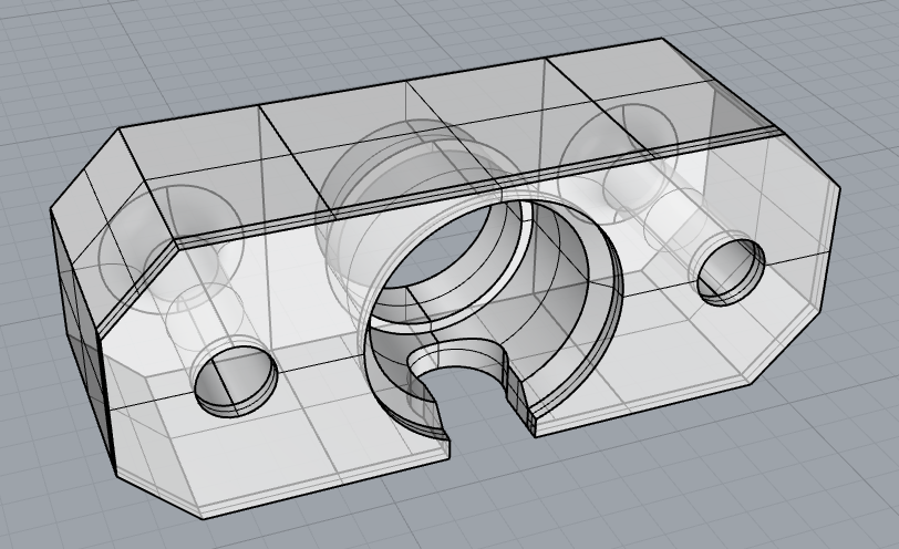
| Gear holder | 1 | |
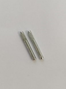
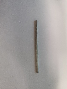
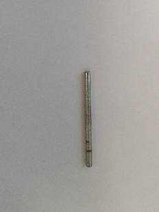
| knurled shaft | 2 |
|
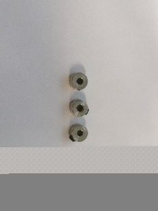
| metal shaft stopper | 3 |
|
gear M=0.5 22mm (42-2A) | 1 | 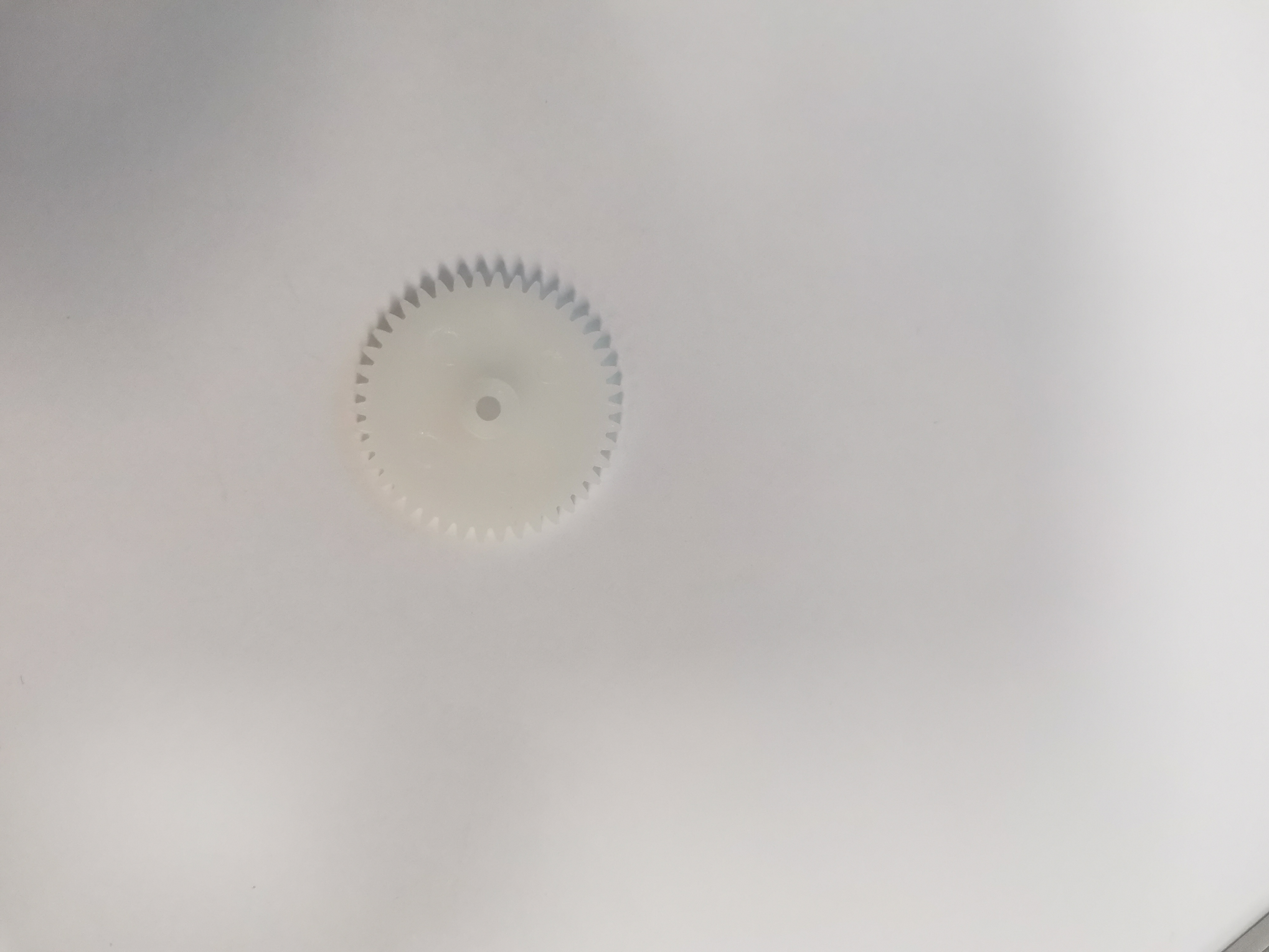 Need to punch by yourself |
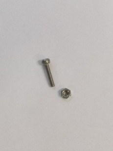
| M2 nut | 6 |
|
| M2 x 10 bolt | 6 |
|
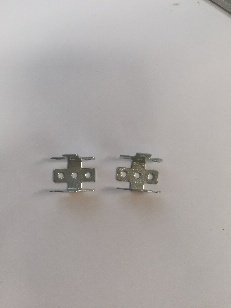
| folded cross plate | 2 |
|
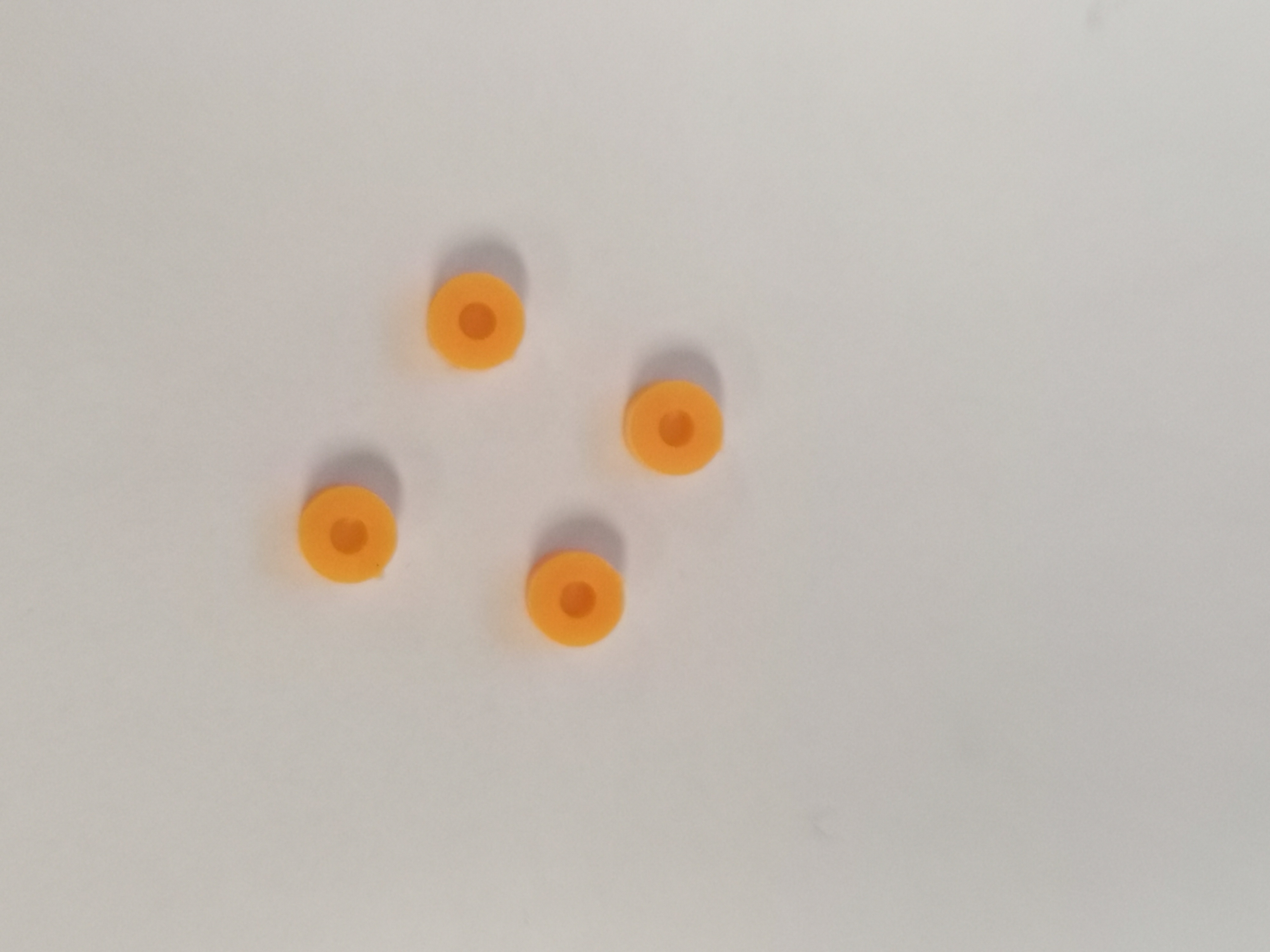
| plastic shaft stopper (M2, orange) | 4 |
|
| shaft (2mm x 70mm) | 1 |
|
| shaft (2mm x 30mm) | 2 |
Used for fixing when punching gears |
Assembly instructions:
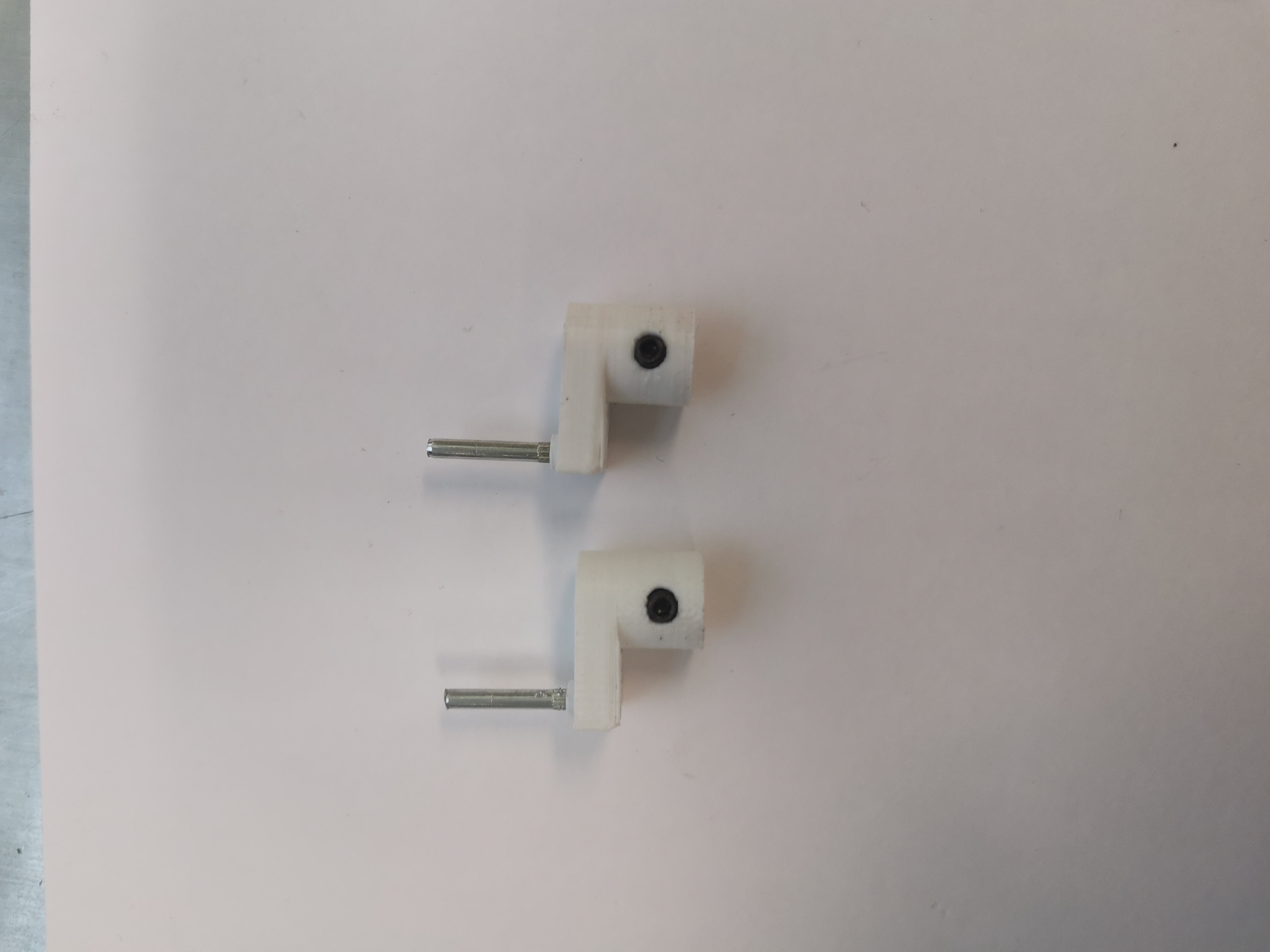
Assemble the crank:
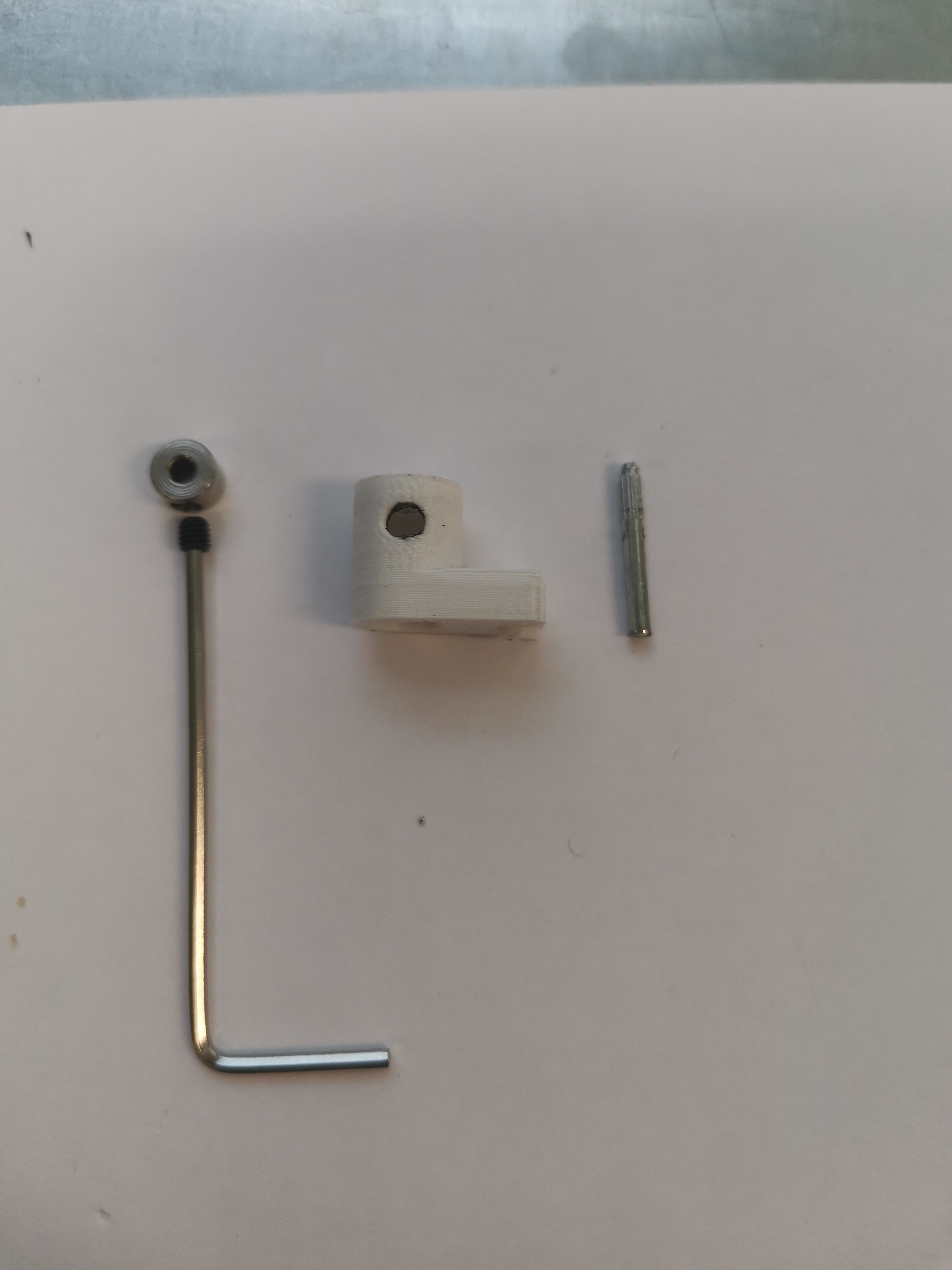
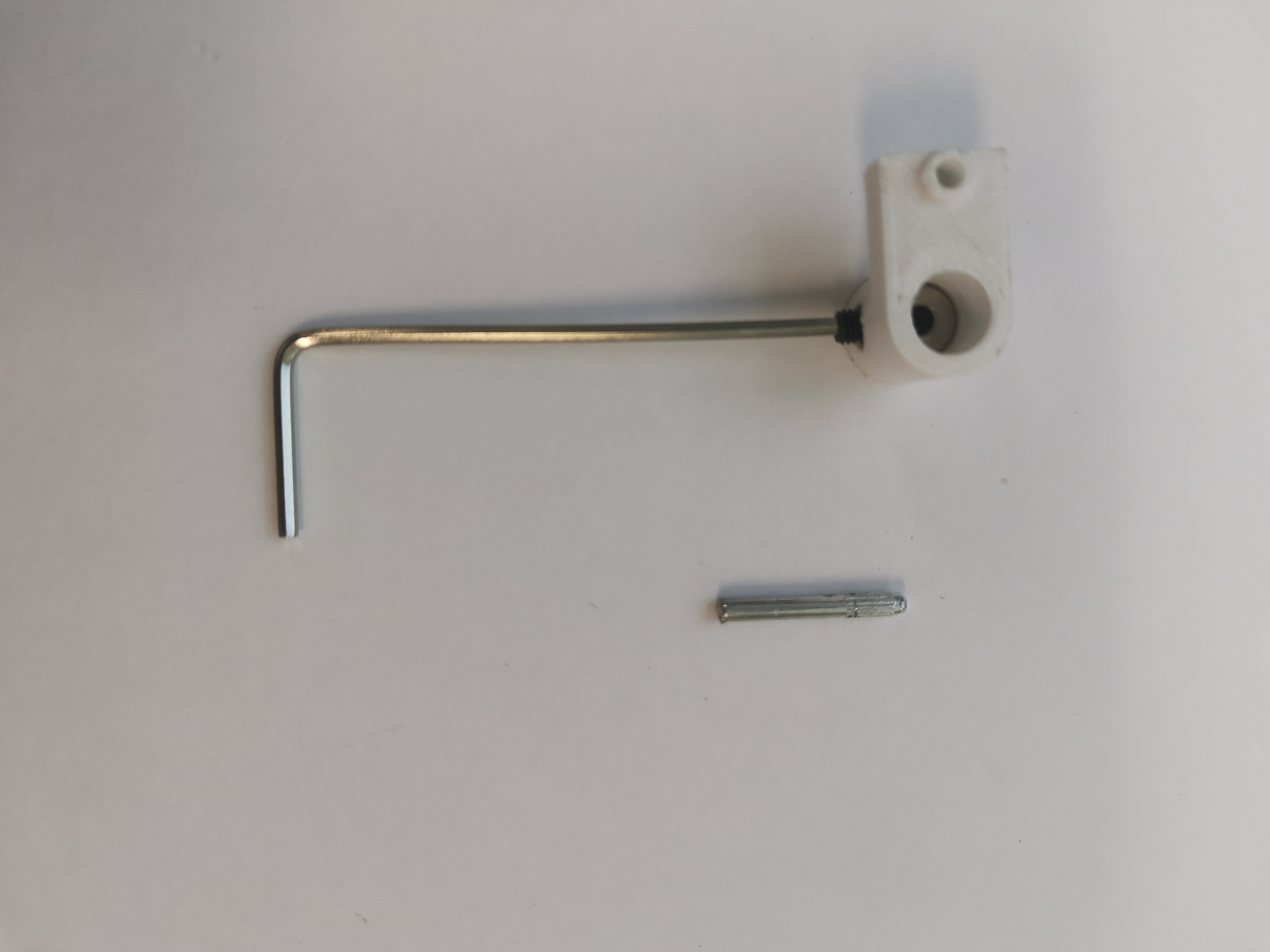
- Components and tool
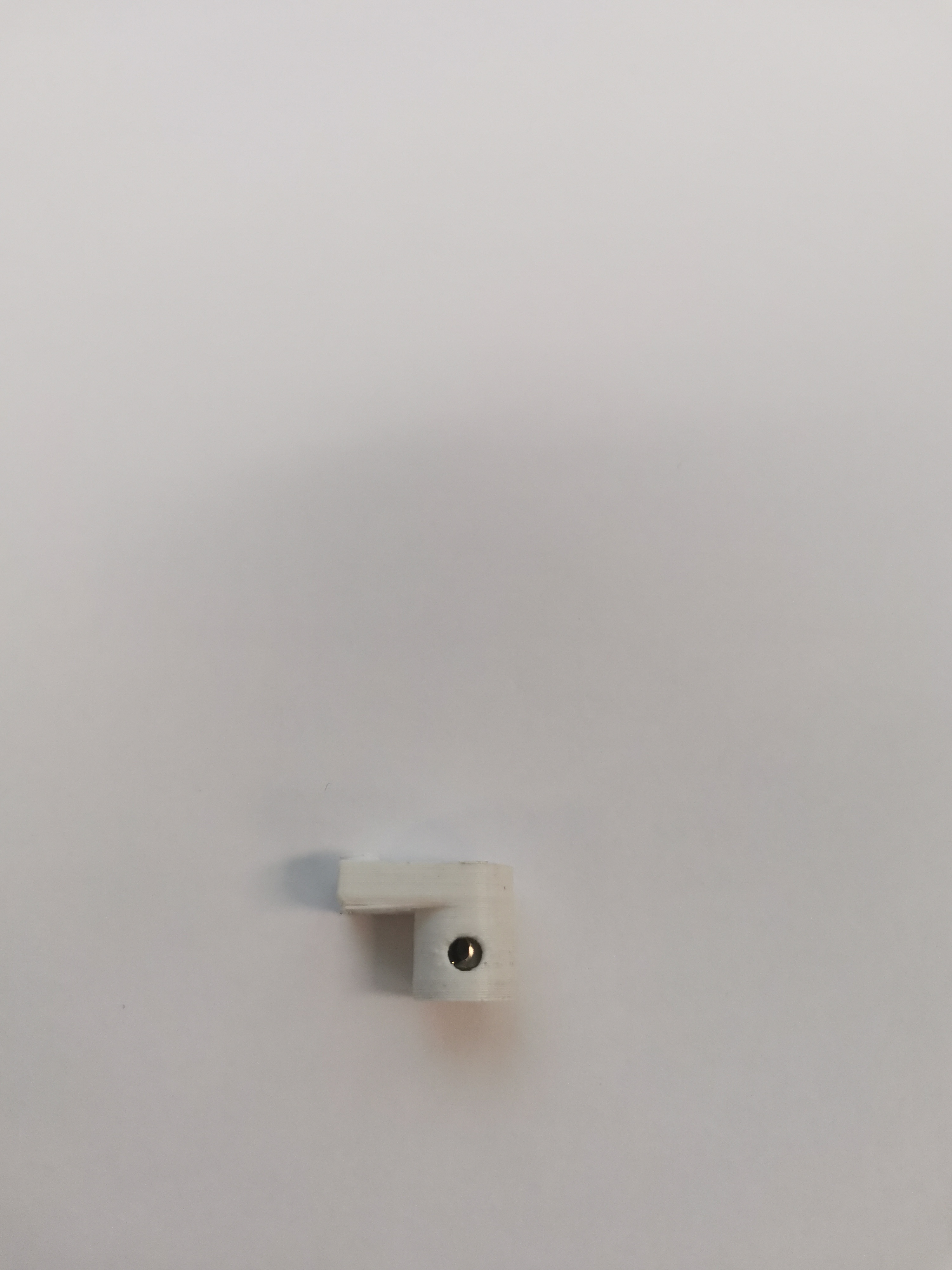
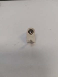
- Insert metal shaft stopper into the crank
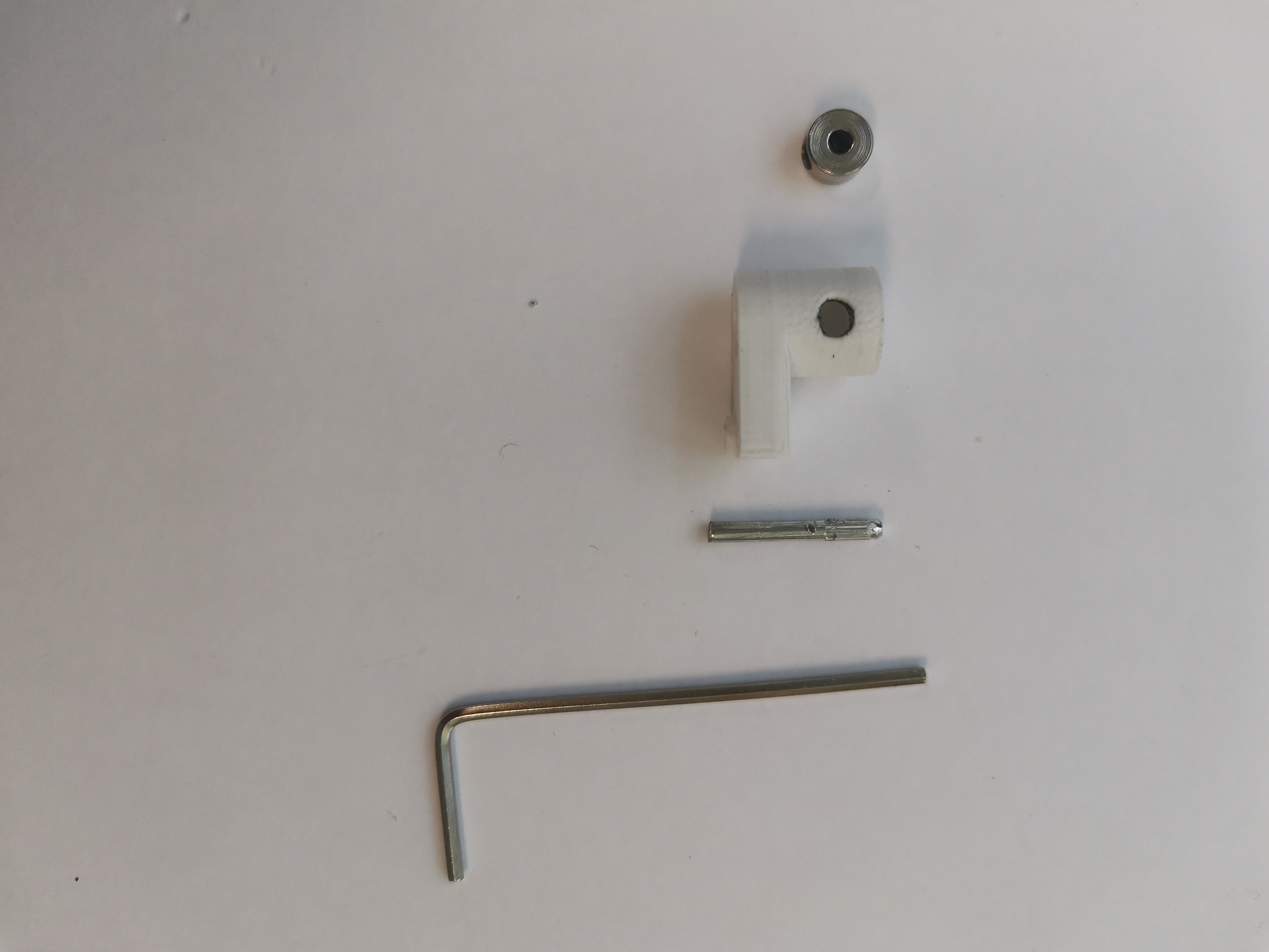
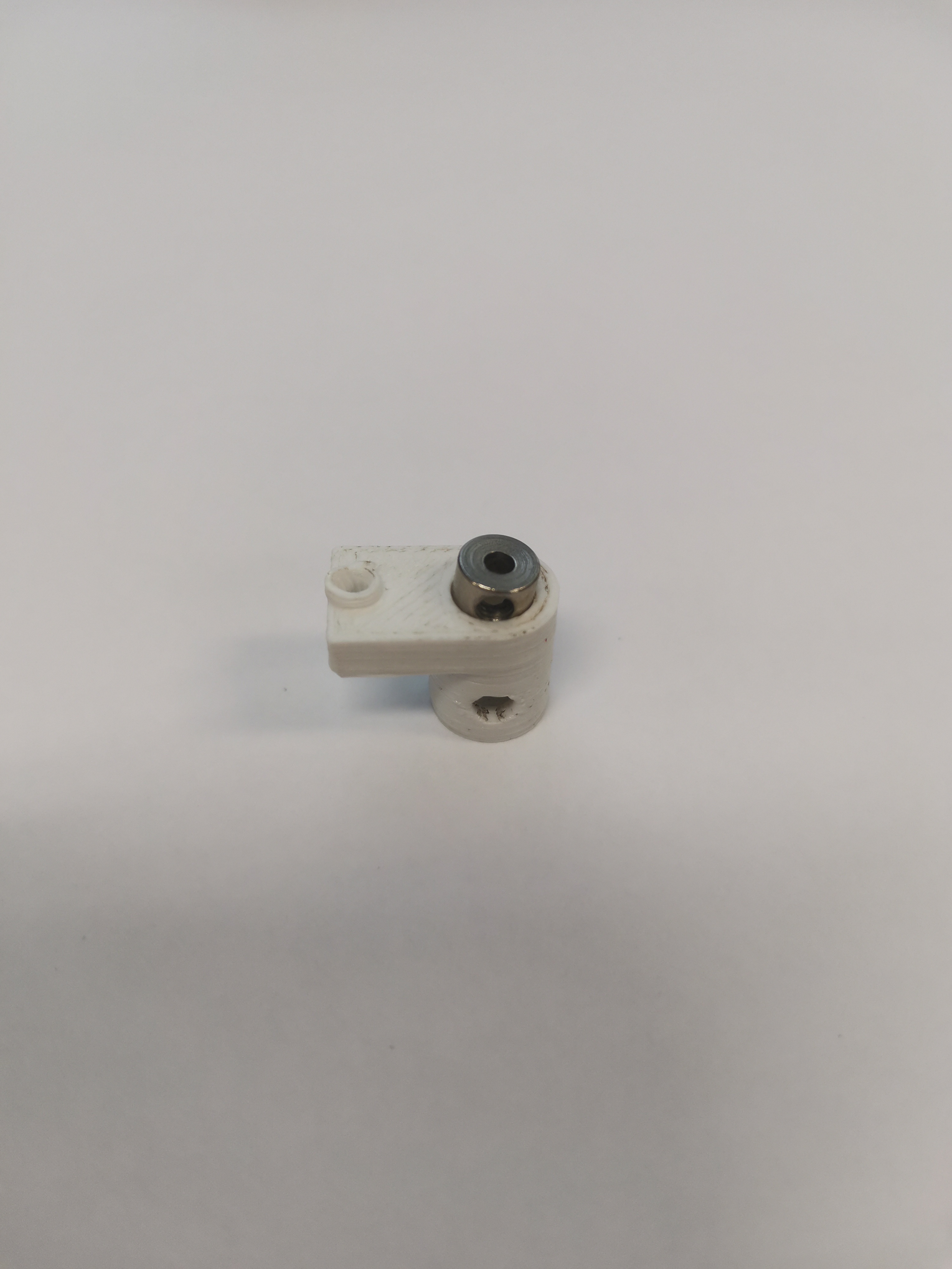
i. Remove the screw from the metal shaft stopper first and align the hole of the metal shaft stopper with the hole of the crank.
ii. The screw will block the metal shaft stopper to be installed into the crank, so you need to remove it first.
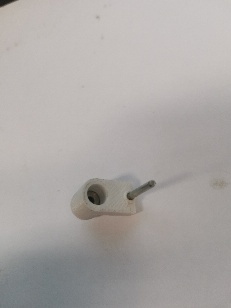
3. Align the screw hole of the metal shaft stopper with the hole on the side of the crank, and insert the screw
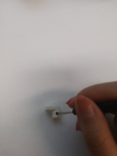
- There may be a deviation between the screw hole and the crank hole. Use a small stick to adjust the alignment.
4. Insert the knurled shaft with a hammer
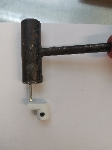
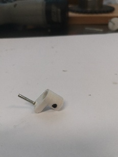
5. Two assembled cranks
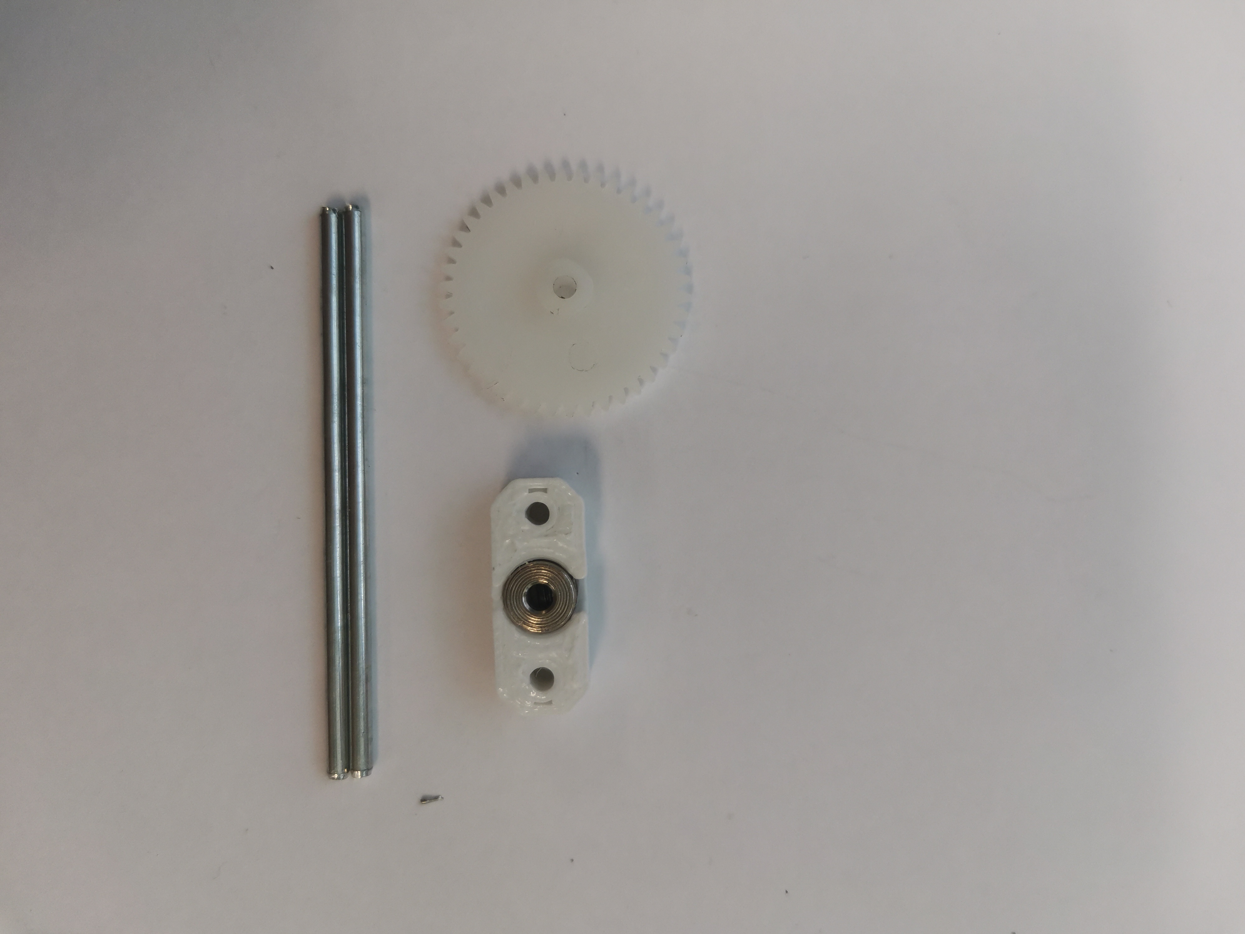
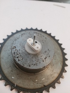
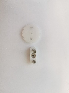
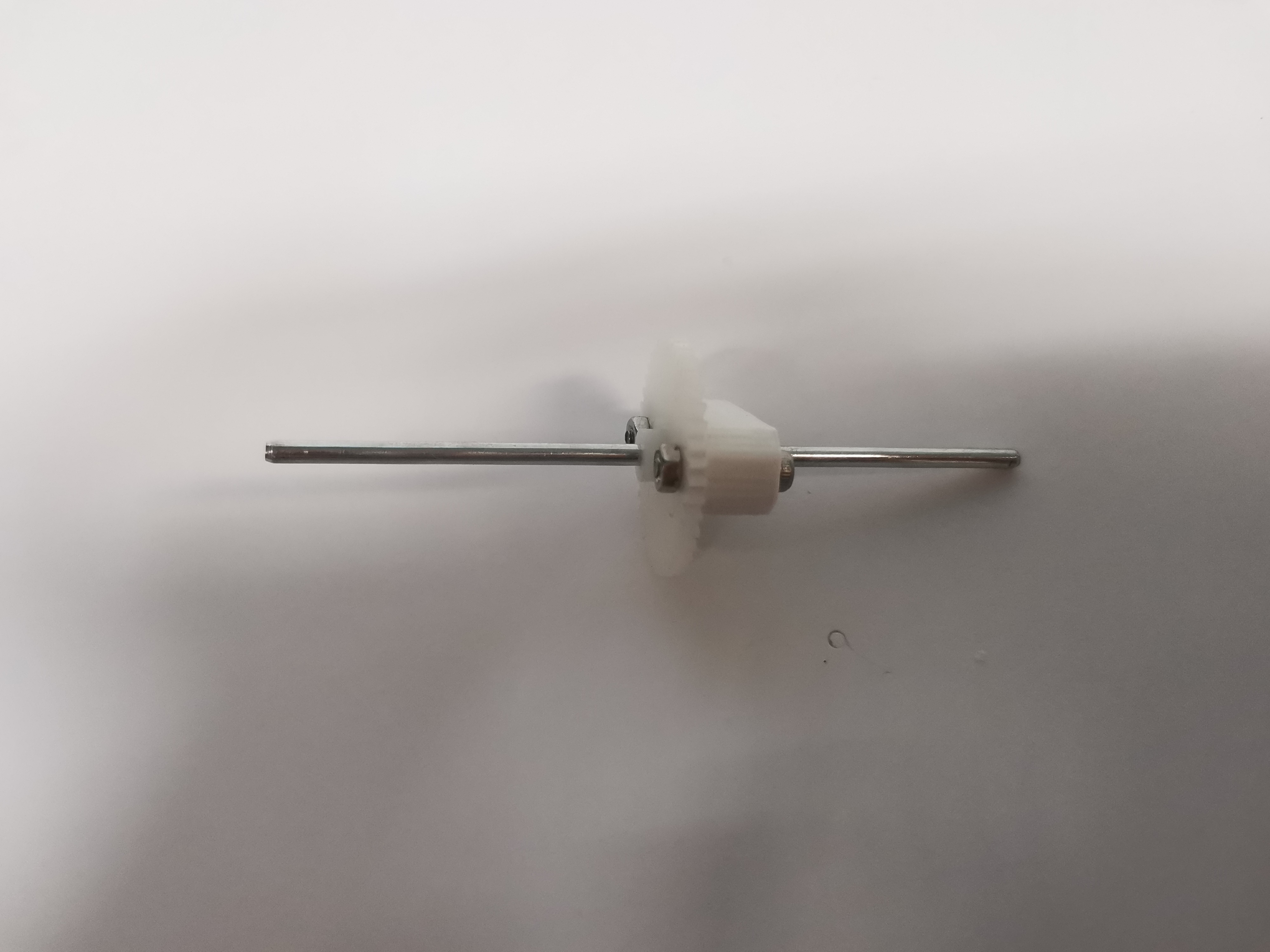
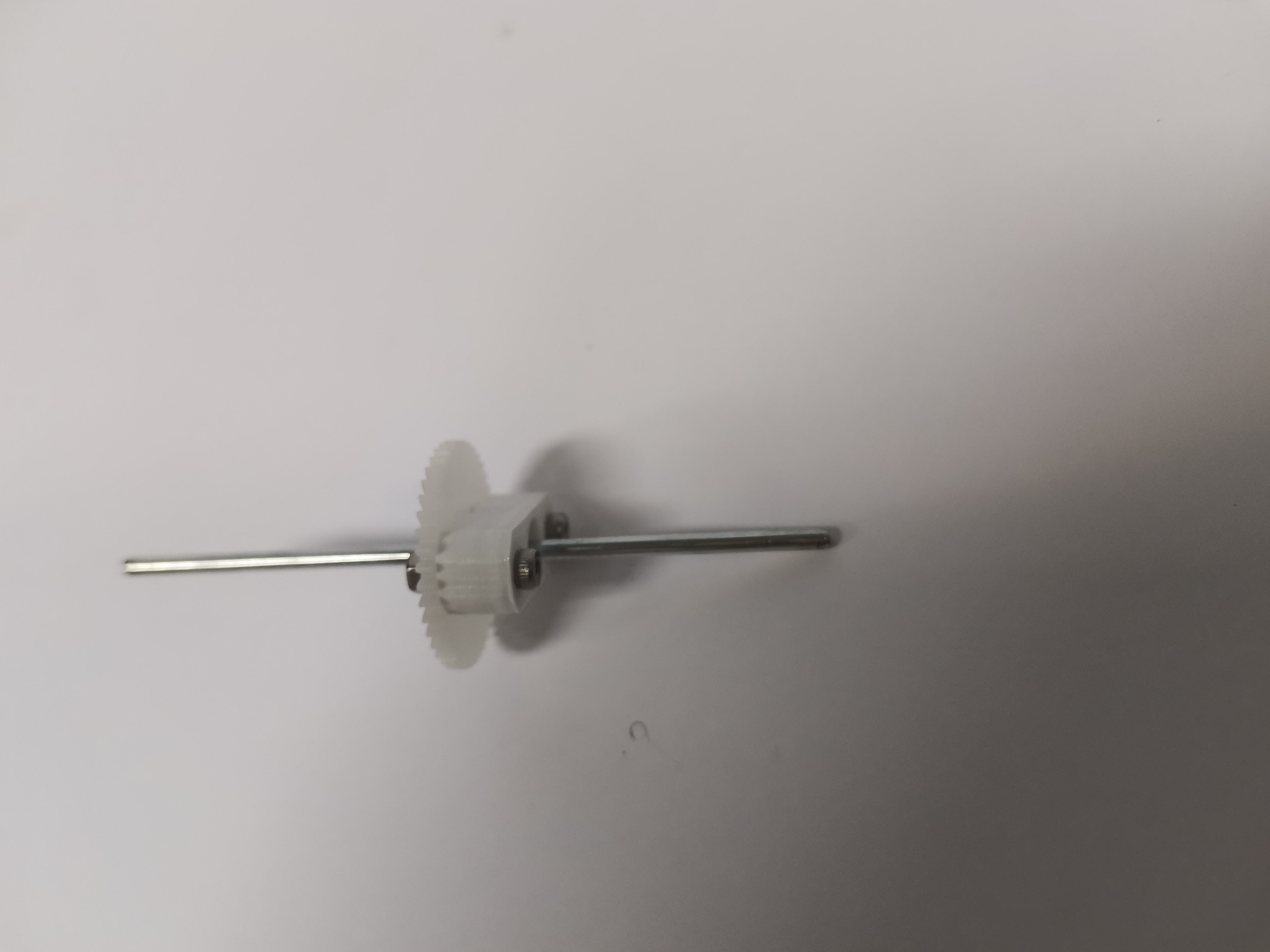
Assemble the gear and the gear holder:
- Components and tools
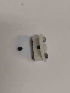
- Insert metal shaft stopper into the gear holder
- Insert shaft to the metal shaft stopper and the gear
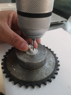
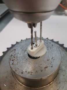
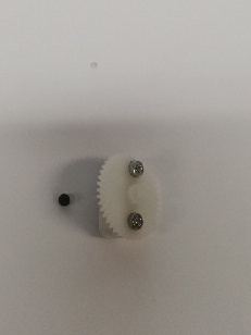
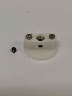
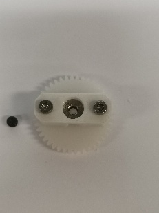
- Align the gear holder and the gear, and drill holes on the gear for putting in bolts. You will need support with holes in the middle as shown
- Put in the bolts and tighten


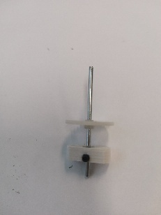
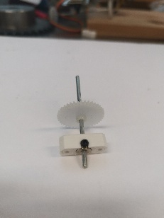
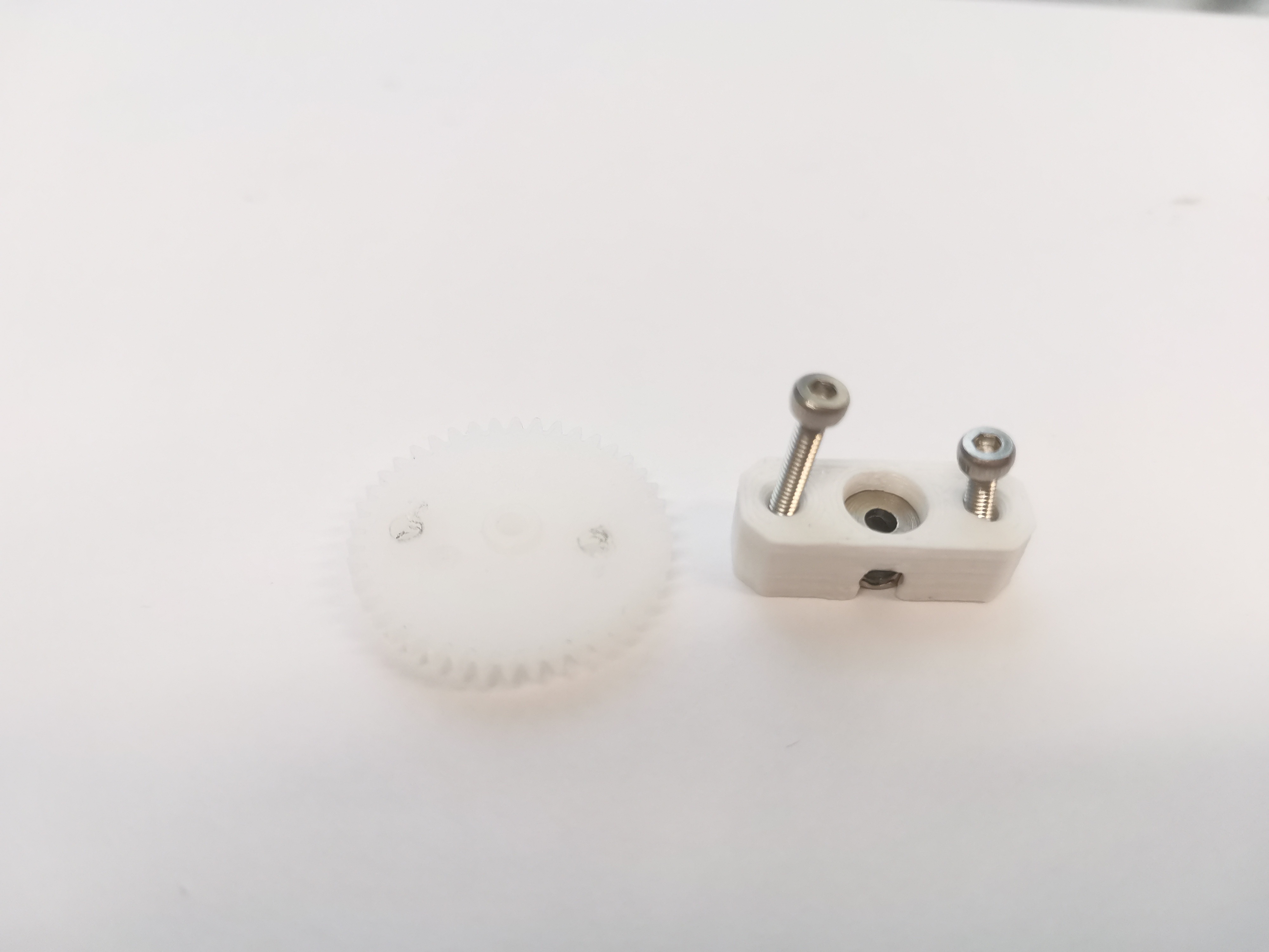
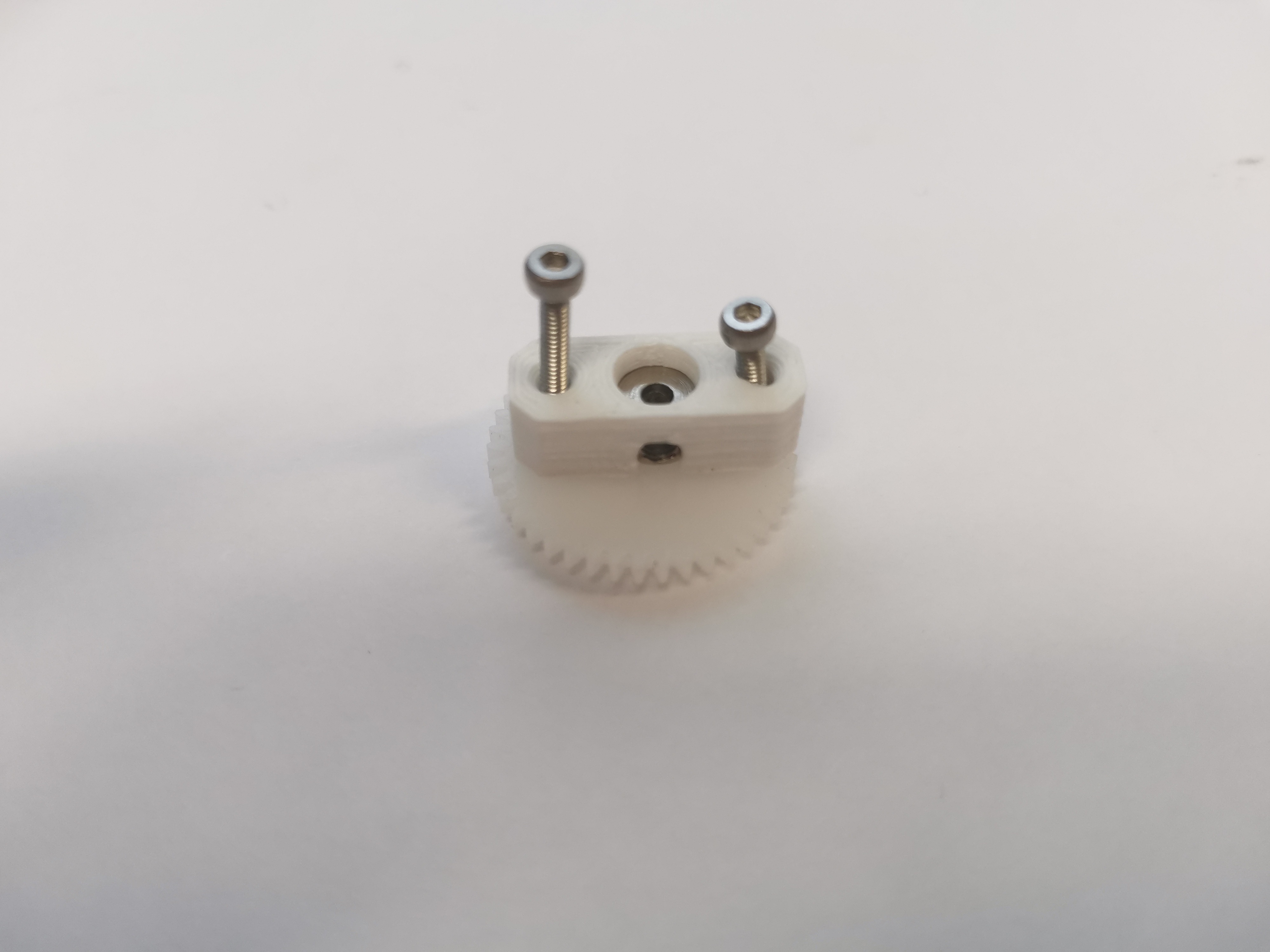
i. Pay attention to the installation direction. Align and assemble the side with the groove of the gear holder and the side with the smaller protrusion of the gear.
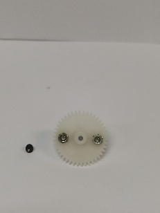
i. Save the screw and install it after the shaft is all completed. Installing the screw in the current step will cause the hole to be locked and the gear cannot be inserted into the shaft smoothly.
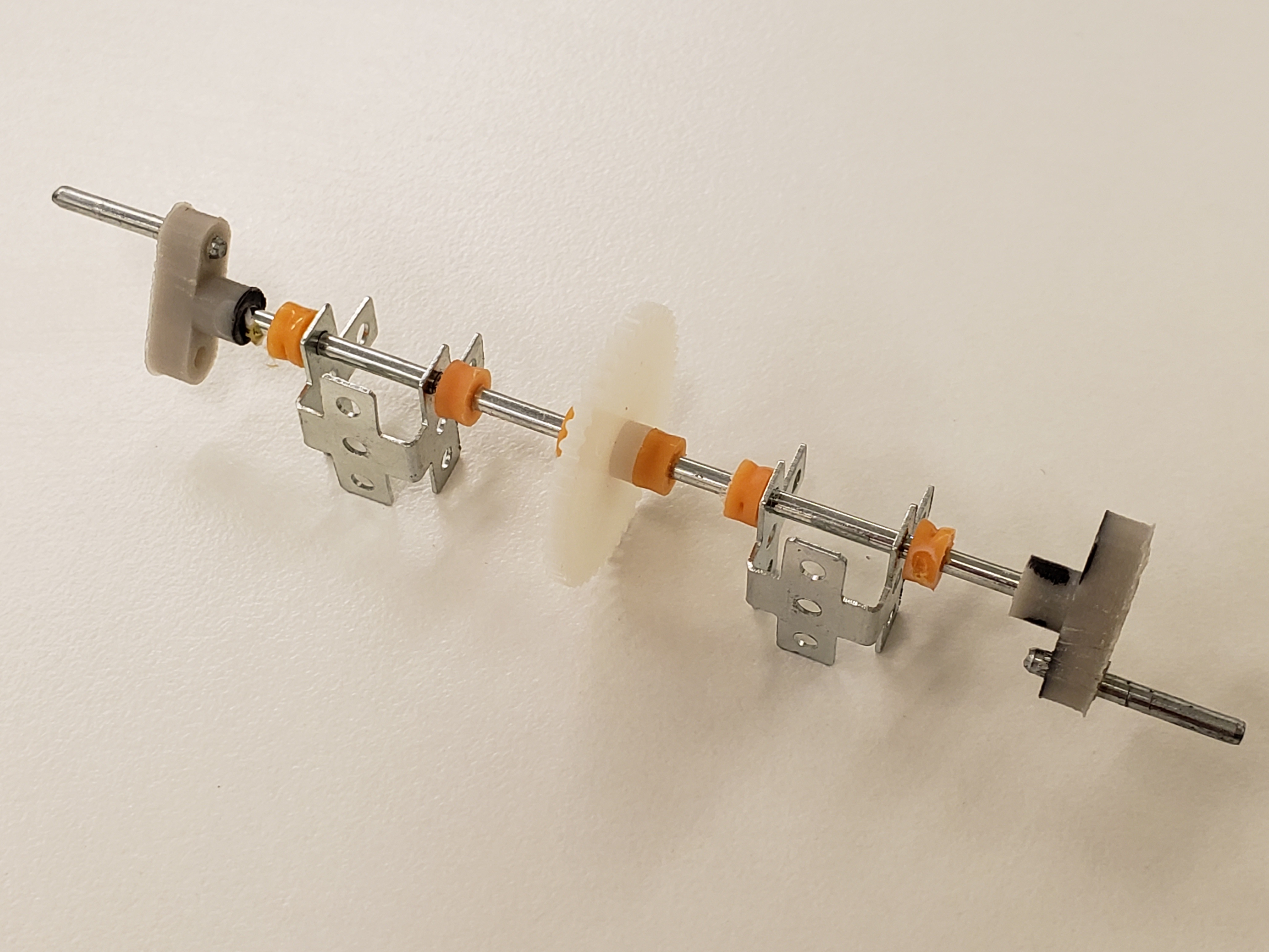
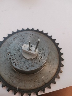
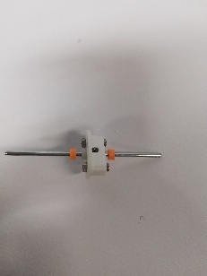
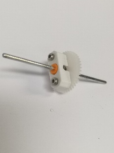
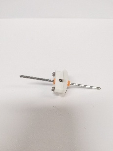
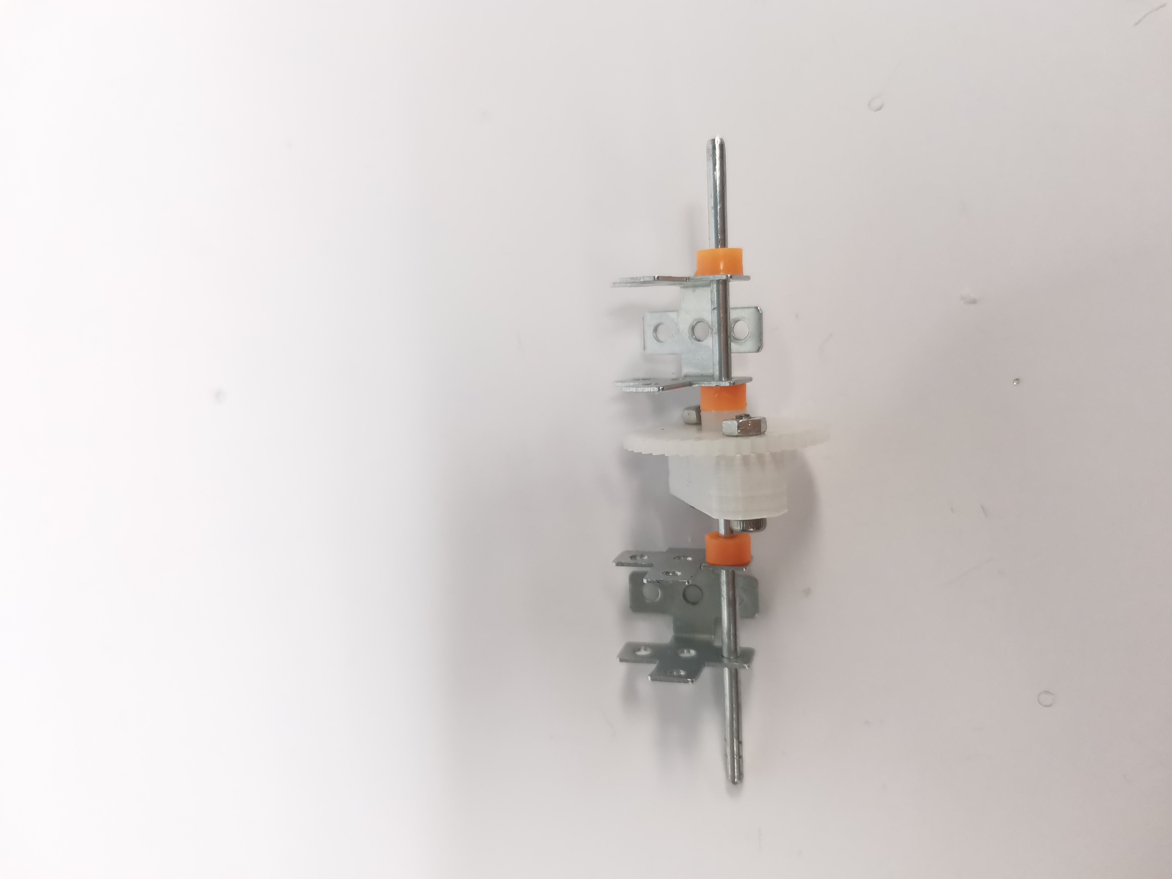
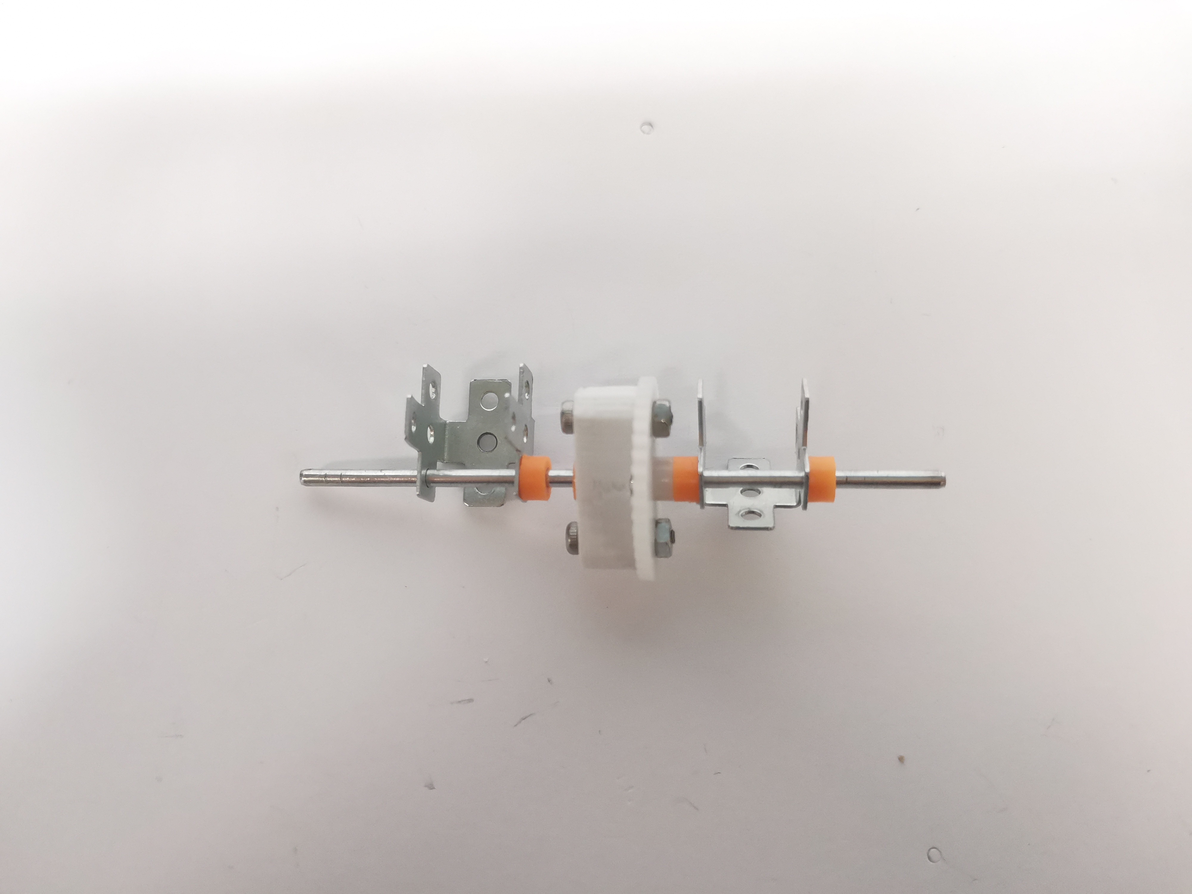
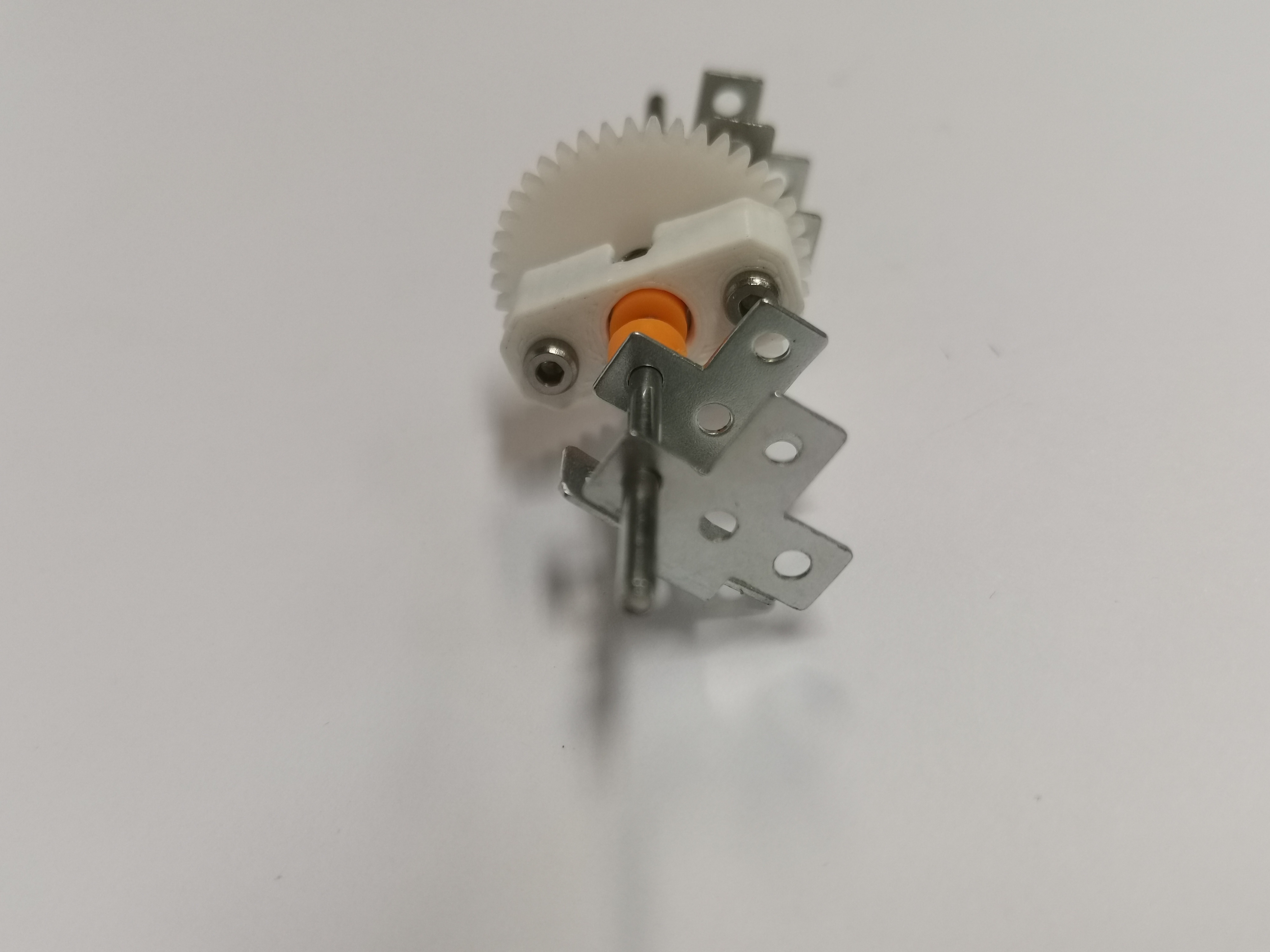
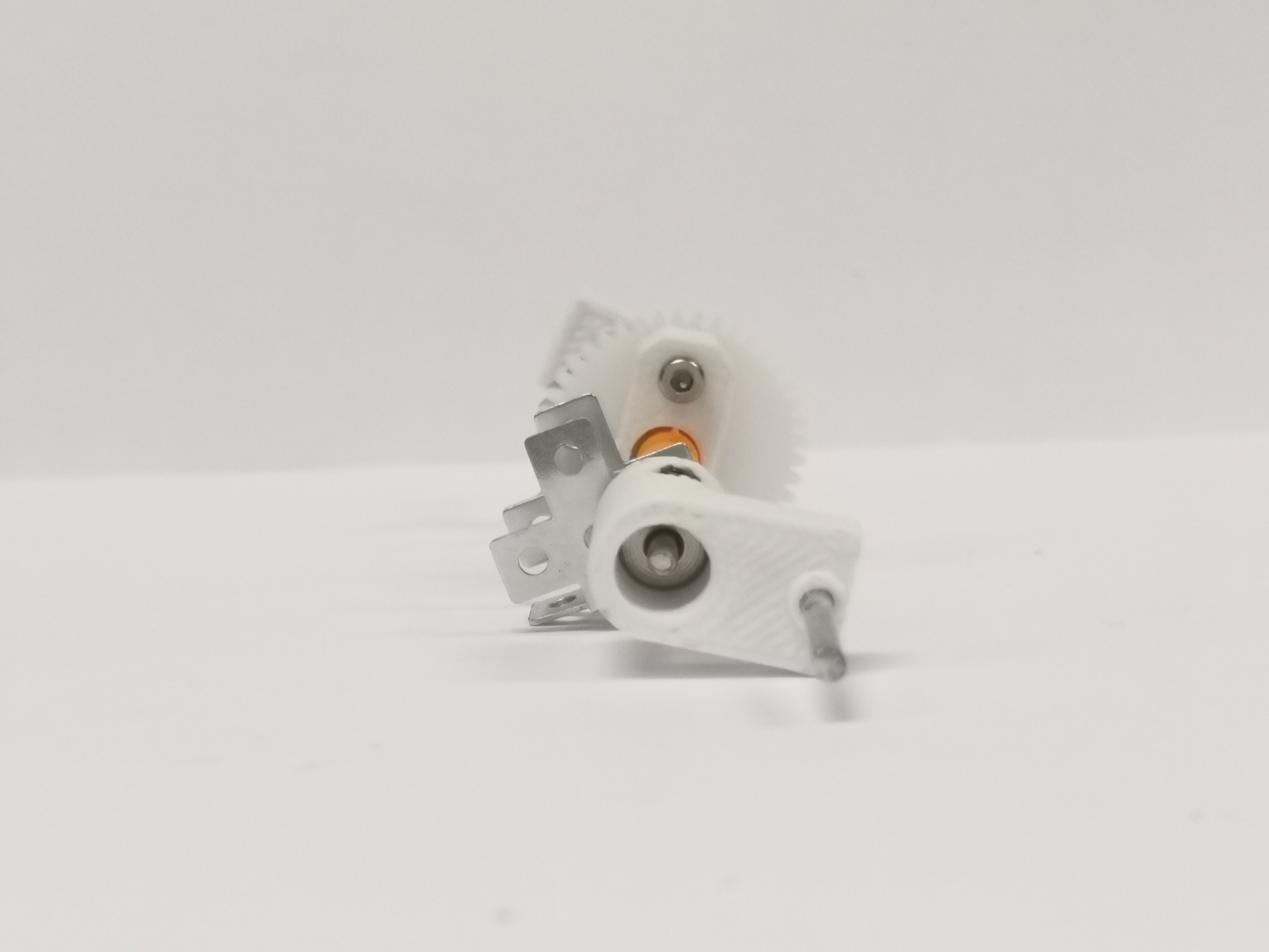
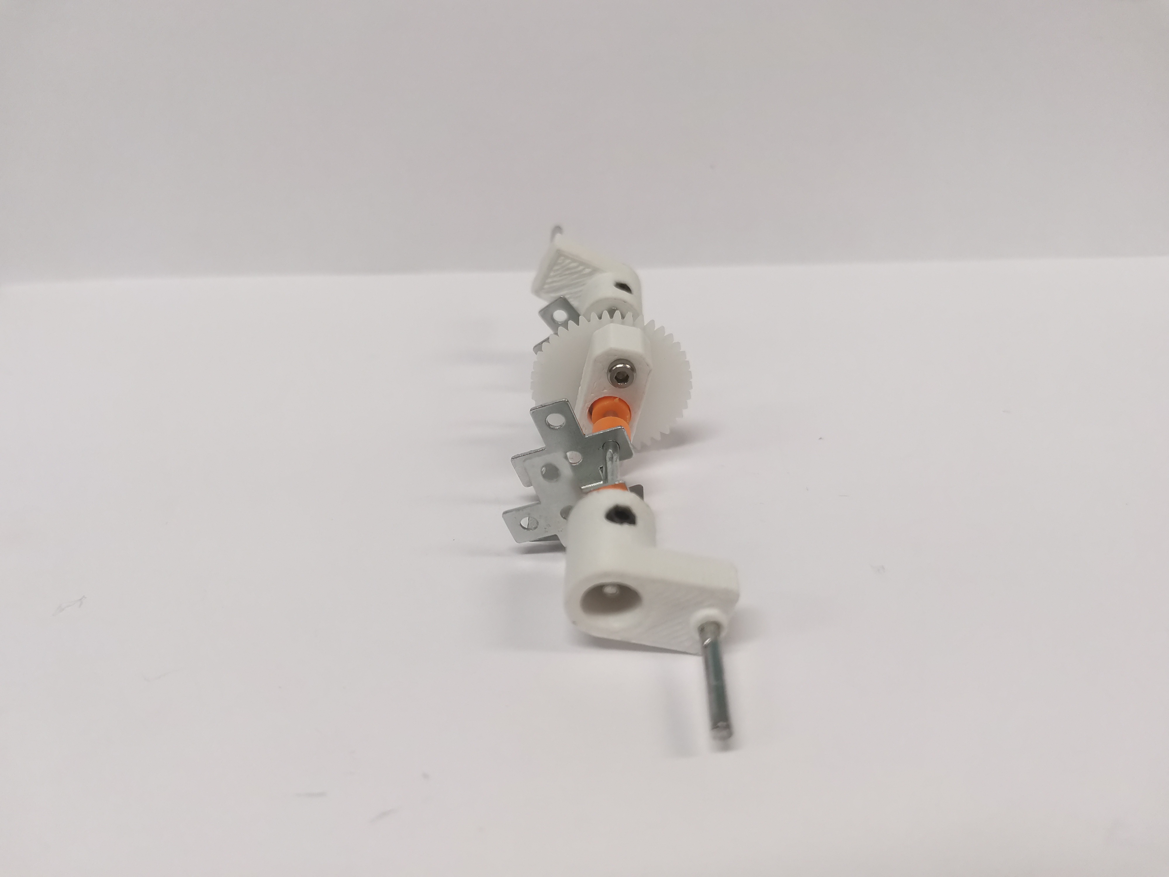
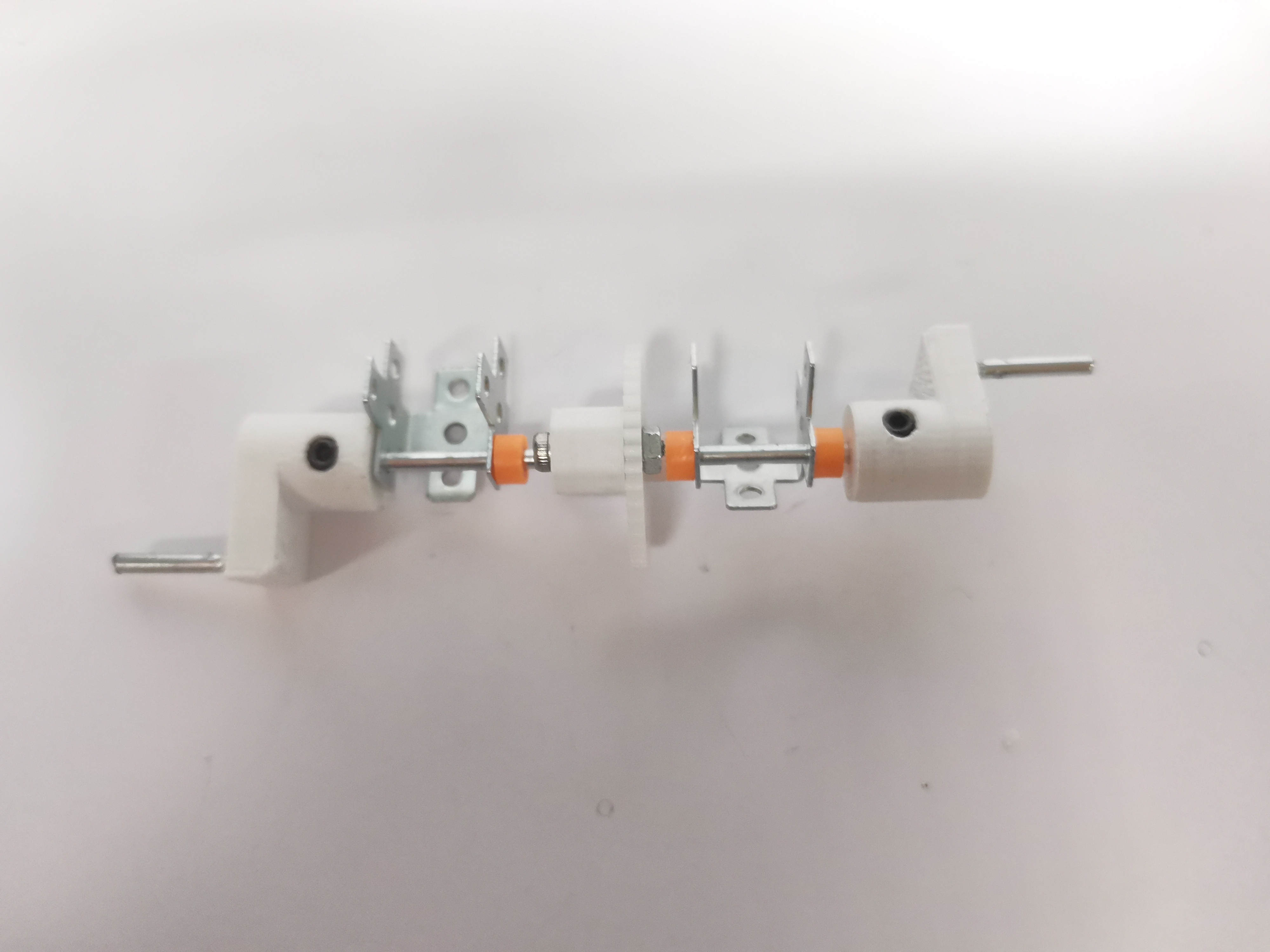
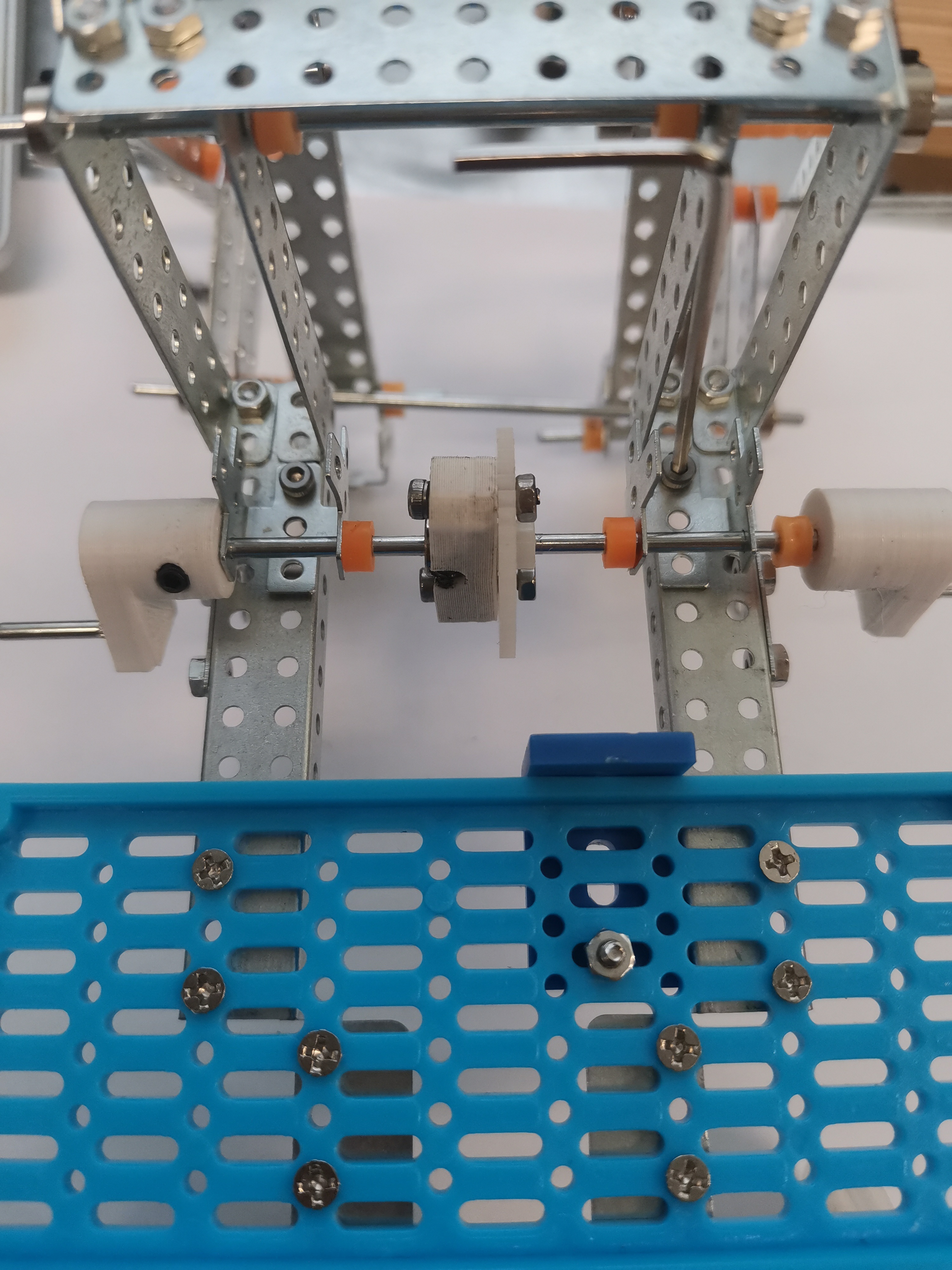
Assemble the cranks and gear onto the main shaft
- Components
- Install the gear first
- Add plastic shaft stopper on each side of the gear
- Install two folded cross plates, and install one shaft stopper beside one folded cross plate. Note the relative position of folded cross plate and gear. when the gear holder is on the left and the gear is on the right, the folded cross plates should be in the up, like the illustration.
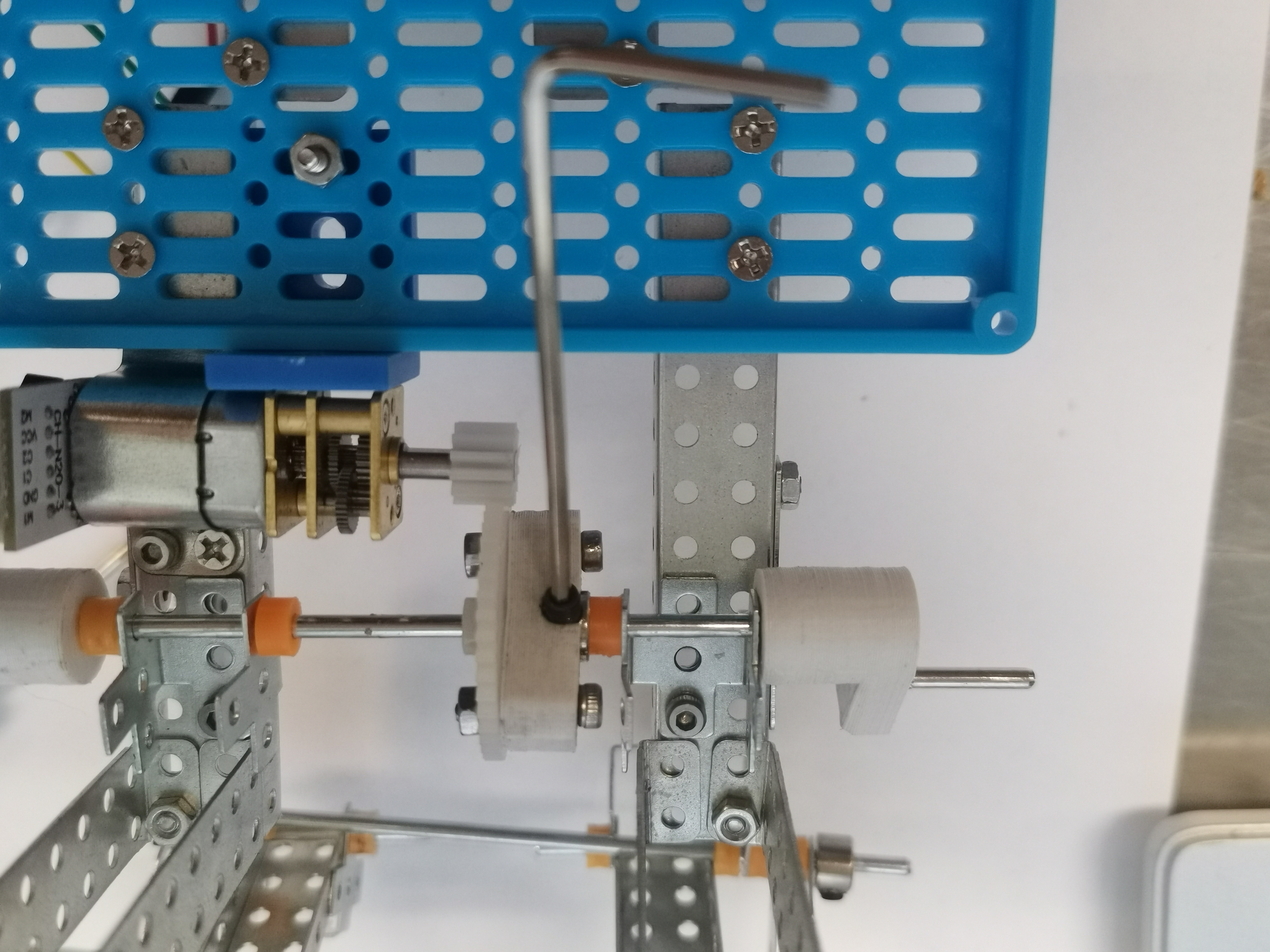
- Install the cranks at both ends, and use the hexagonal key to lock the cranks.
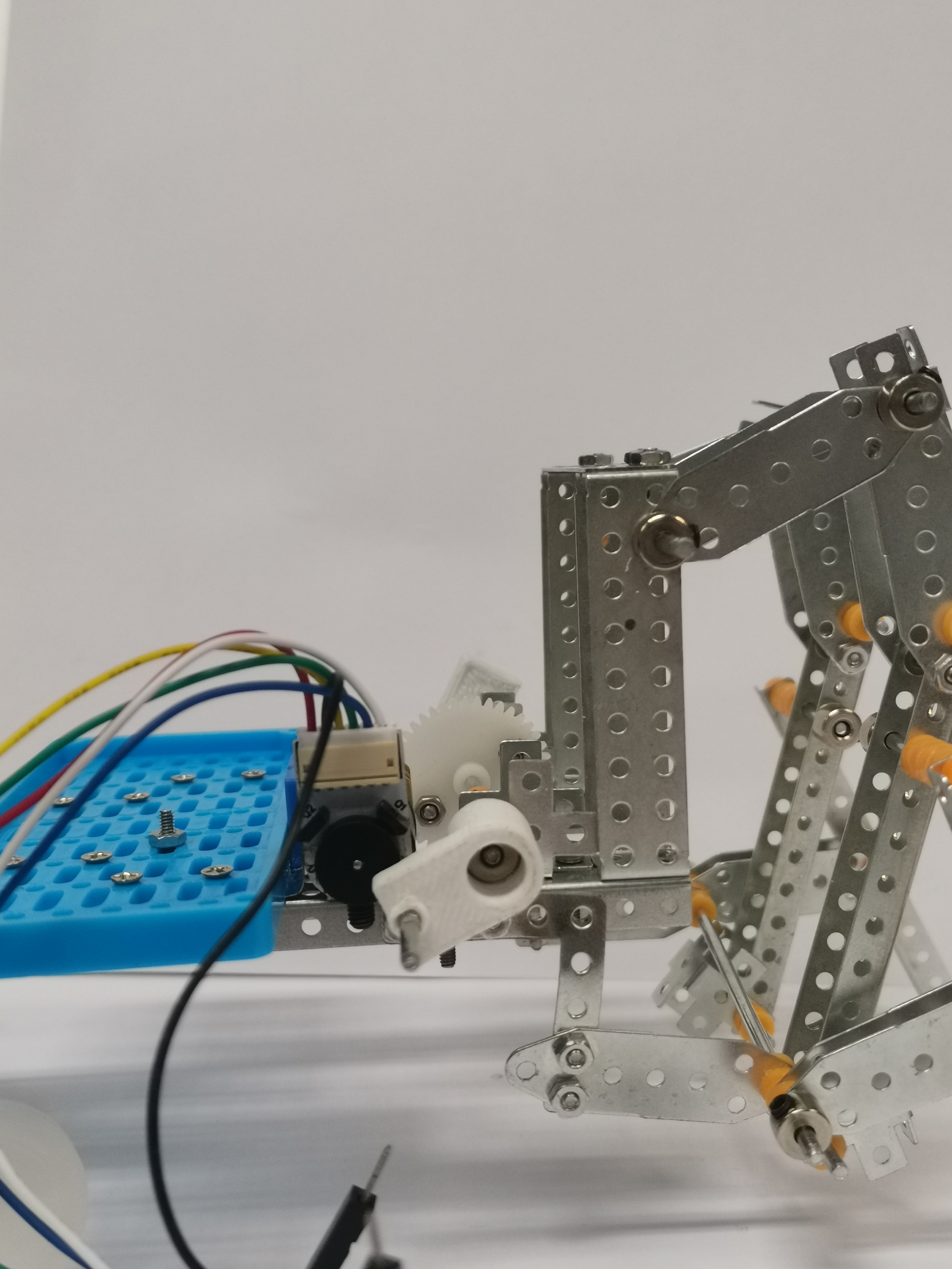
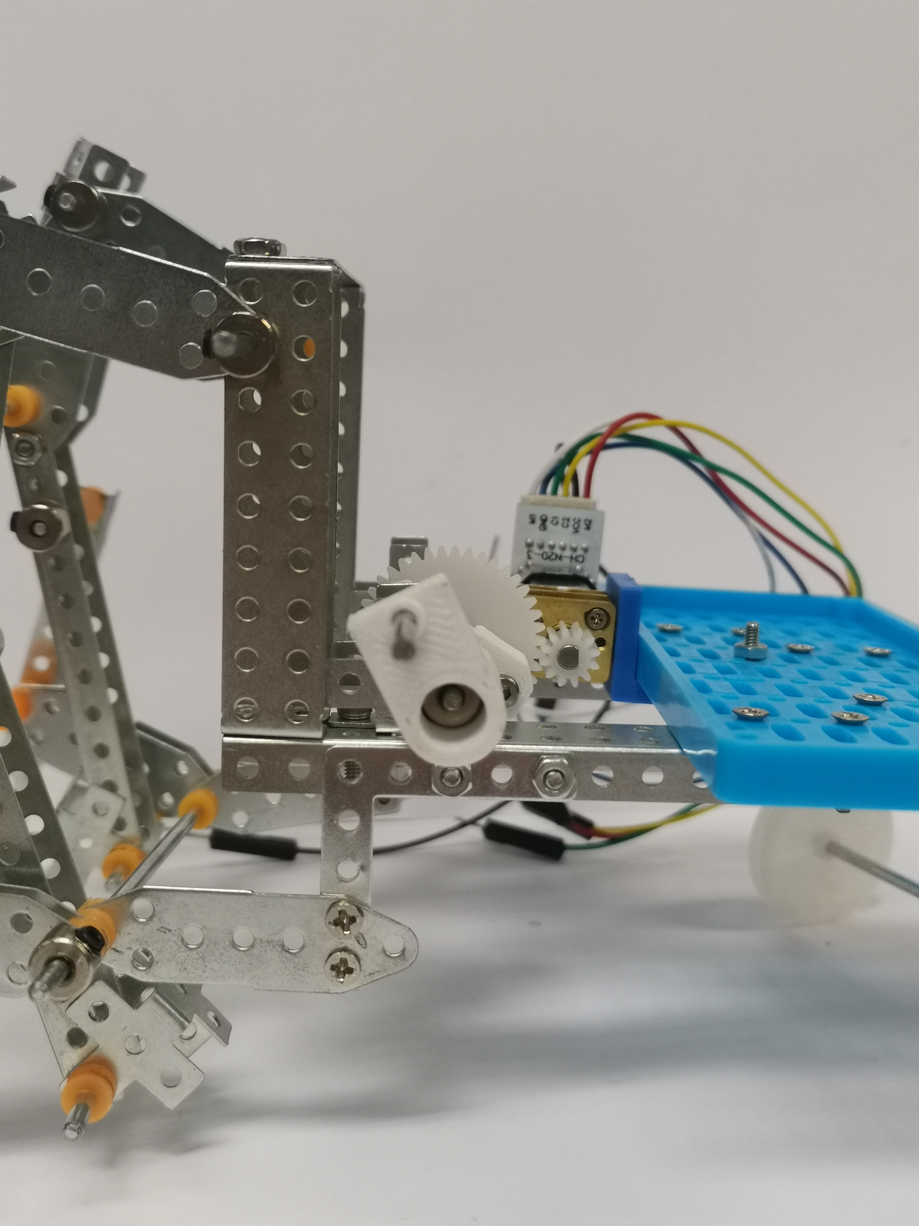
Assemble the main shaft (with new crank and gear) to the main body
- Adjust position of the gear to align with the motor and tighten the screw on the metal shaft stopper in the gear holder. Note that the motor must be pushed towards the inside as much as possible, so as not be block the crank
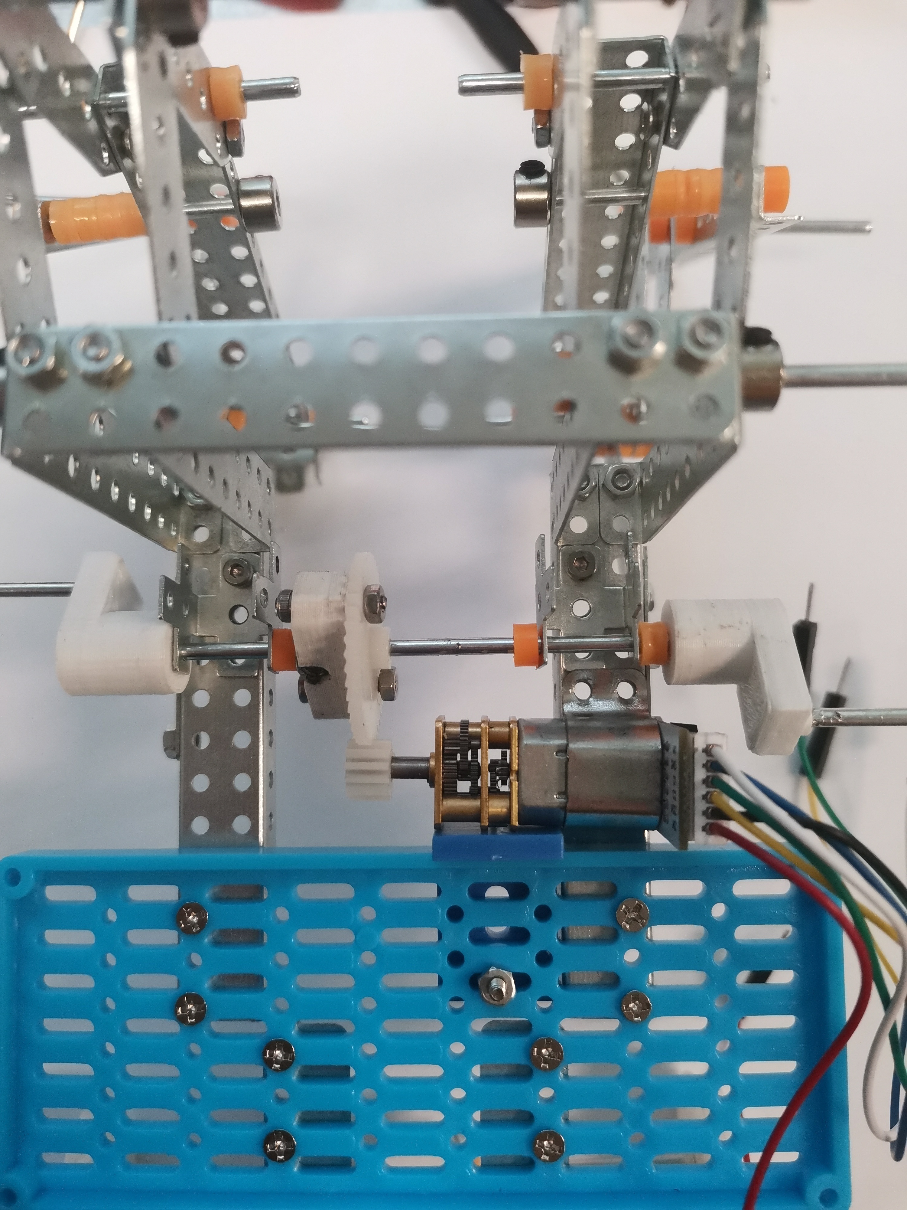
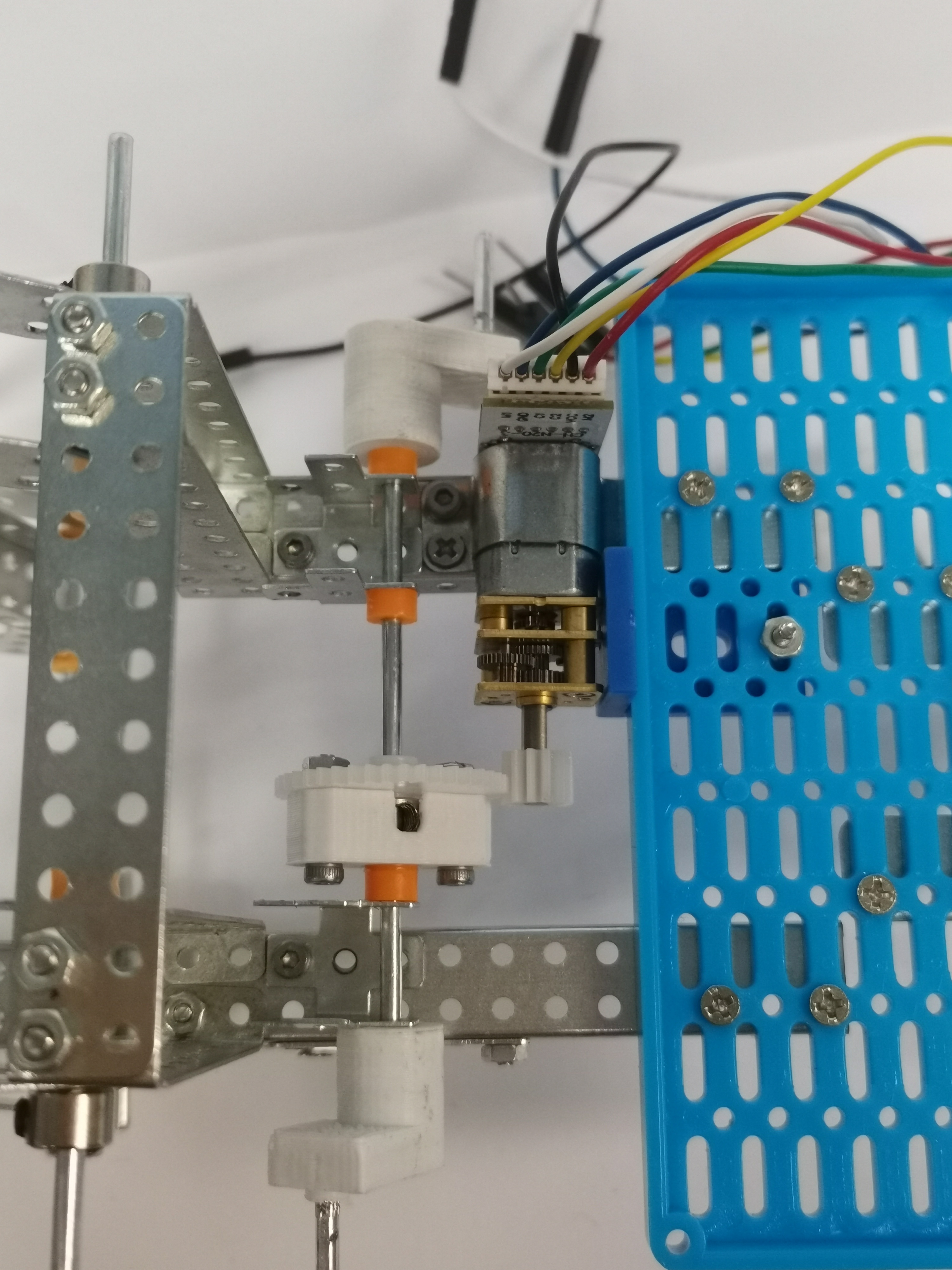
i. Adjust the bite position of the gear and the motor suitable before installing the screws to ensure the gear is stable.